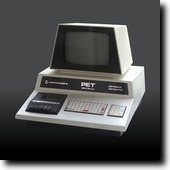
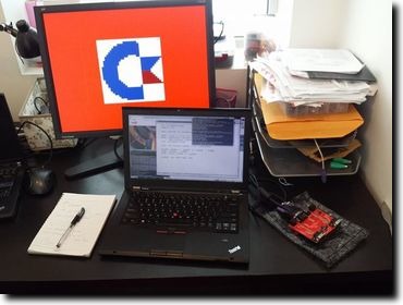
Initial version of my Commodore PET
2 March 2015 (programming haskell fpga electronics retro)In my quest to build more and more complicated computers on FPGAs armed with nothing but a crappy hobbist mindset and some hazy ideas of how Kansas Lava is supposed to work, I've reached another milestone: my first real computer.
That is, unlike the Brainfuck CPU that I designed myself, or the CHIP-8, which was originally a virtual machine spec (with all the implementation leeway that implies), this latest subject is a bona fide 8-bit home computer from the seventies: the Commodore PET.
The Commodore PET in a nutshell
The PET is a very simple machine compared to later Commodore models, which is why I thought it would make a good first step on a journey that I hope will one day culminate in implementing a Commodore 64. Its centerpiece is the MOS 6502 CPU (practically the same as the MOS 6510 used in the C=64), and there are only four other components: a text-only video signal generator and three IO interface chips (two PIA's and one VIA) for keyboard, Datasette and extension port communication. Just hooking up one of the PIAs is enough to get a minimal system working with keyboard input.
12 KBytes of PET ROM contain implementation of basic IO routines (the so-called "kernal"), the full-screen text editor, and Microsoft's BASIC interpreter. Then there's a separate character ROM (not addressable from the CPU) used by the video generator.
MOS 6502
The 6502 microprocessor was a staple of the eight-bit home computer era of the late seventies and eighties. By today's standards, it is incredible to imagine what it must have been like to design it manually, drawing the layout with pencils on paper. On the other hand, if it was designed in such a low-tech way, I figured it shouldn't be too difficult to build something compatible using modern tools even by a hobbist like myself. And of course there are already dozens of home-built 6502 implementations out there, to varying degrees of compatibility.
The ultimate reference on the 6502 must be the Visual 6502 Project which I deliberately avoided consulting. I don't really see the educational value in copying the original 6502 design; so instead, I went with a more black-box approach by just looking at the opcode descriptions and interrupt model and working from that.
The first milestone I aimed for was to get enough of the CPU working that I can run the sample programs on 6502asm.com, which defines a tiny microcomputer-like architecture that doesn't have interrupts or any fancy video modes: you just have 32×32 pixels with a fixed 16-color palette mapped to main RAM from $0200, and a zero page-mapped register for keyboard input that you can do polling on. The Kansas Lava implementation is really simple and I plan to reuse it later if I do a similar project with the Z80.
My workflow was that I would use ca65 to assemble test programs, burn them into ROM, and run it in the Kansas Lava simulator for a couple thousand cycles; then render the video RAM into a GTK+ window. I would start with this program that does nothing but moves data around in memory (drawing the Commodore logo pixel by pixel), and basically I implemented the 6502 opcodes as I went along. After two days of work, I finally got it working:
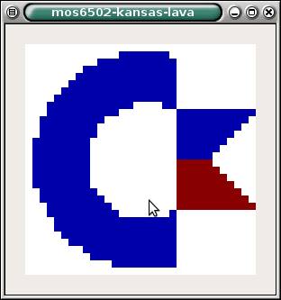
Seeing this was an incredible feeling. The input was valid 6502 machine code, and my very own CPU managed to run it correctly for the approximately 40,000 cycles that it took to draw this image. There was no stopping at this point: I already had a working VGA frame buffer implementation from the CHIP-8, so next day I synthesized it and run it on real hardware, my venerable Papilio Pro:
Simulation-based testing
As I added more and more opcodes and started running more and more complicated programs, things very quickly stopped working. My CPU was full of bugs, and figuring out what went wrong by looking at the simulation logs after running it for tens of thousands of cycles was very tedious.
And so, it was at this point that I started adding unit tests. The framework for writing tests exposes a monad where the available effects are making observations on the state of the system (CPU registers and contents of the memory) and executing instructions. This presents an API that allows writing tests in an imperative way:
php = do
    flags <- observe statusFlags
    sp <- observe regSP
    execute0 0x08
    sp' <- observe regSP
    pushed < observe $ mem (stackAddr <$> sp)
    assertEq "Stack pointer is decremented" sp' (pred <$> sp)
    assertEq "Status is correctly pushed" pushed flags
A test like this is turned into a ROM image containing $08 at the address pointed to by the reset vector. The simulation is then run until the CPU enters the Fetch internal state for the second time (the first time is when it fetches the opcode under testing, i.e. the PHP ($08) instruction), and then the observations are evaluated by looking at the simulation output in the same cycles as the Fetch state. Of course, this means you shouldn't be able to write tests like the following:
impossiblyDynamicTest = do
    arg <- observe regX
    execute1 0x00 arg
    a' <- observe regA
    assertEq "A is updated" a' arg
This is ensured by observe returning values wrapped in an Obs type, and execute1 requiring unwrapped arguments:
observe :: Query a -> TestM (Obs a)
execute1 :: Byte -> Byte -> TestM ()
assertEq :: (Eq a, Show a) => String -> Obs a -> Obs a -> TestM ()
To allow assertions over derived values, Obs is an applicative functor (in fact, it is the free applicative functor over the co-Yoneda functor of the primitive observations).
I think this approach has merit as a general framework for hardware simulator-based unit testing and I intend to extend it and maybe even carve it out into a separate library in the future.
A Minimal Viable PET
Once I had a sufficiently working CPU, I started building the other pieces around it. I took the PET emulator from the VICE suite and commented out all the PIA and VIA code, replacing writes with nops and reads with hardcoded values, until I was able to boot it up with the stock ROM to get to the READY. prompt. Of course, since the PIA supplying the interrupt used for timing was removed by that point, I had no flashing cursor or keyboard input. All in all, the system got to a steady state in about 80,000 operations. (Since my implementation is not yet cyle-accurate, I had to switch to counting operations instead of cycles beyond this point. Every operation is at least as fast as on the real chip, so I hope by adding some wait cycles I'll be able to take care of this at some later point.)
After hooking up the same hardcoded values on the same addresses to the CPU, the next step was running the simulator and peeking at the video memory area ($8000..$8FFF on the PET), using the original fonts to render the screen. The initial version showed there might be someone home (sorry for crap quality on the screenshot):
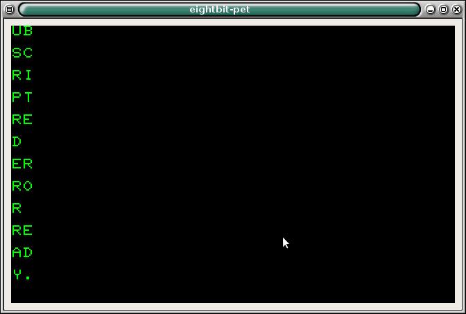
By comparing detailed logs from running the emulator and the simulator, I was able to make observations like "the first 12,345 steps seem to be in agreement", which was a big boost to productivity, getting me, in short order, to this:
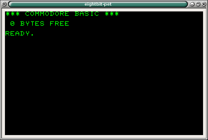
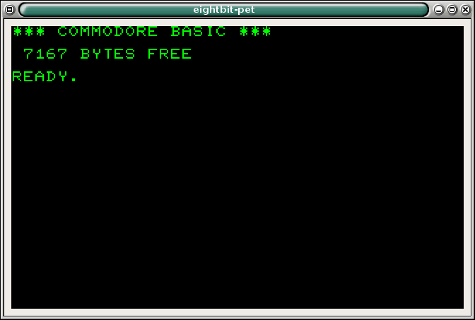
After fixing some more bugs in the arithmetic opcodes, I was finally rewarded by this sight:
Adding more components
While working on the CPU, I also started writing the character generator, on top of the VGA signal generator in the kansas-lava-papilio package that I originally made for the CHIP-8. This way, the VGA synchronization signals were abstracted away from me and I just had to take care of pumping out the actual pixels. This turned out to be tricker than I originally thought, since you have to time all read-aheads just right so that everything is at hand just in time for the next pixel. So before it finishes drawing the 8 pixels that make up a single row of a character, the next character index is loaded from RAM, and then the character ROM is consulted for the first row of the font image of the next indexed character. Initial versions were having some ghosting issues, or even more fun, full character transpositions (like showing the character from one line above in the first position of each line).
The Commodore PET diverts the vsync signal from the video generator to one of the PIA chips, which generates a CPU interrupt that can be acknowledged by reading from one of its memory-mapped registers. So the next obvious step was to implement this functionality to get the cursor blinking! This required more than just implementing a PIA, since I didn't even have interrupts in the CPU at that point.
But all that work was totally worth it:
And now, here we are
The current version supports keyboard input from PS/2 keyboards (but not all keys are mapped yet), so for the first time since I started working on this more than a month ago, it can be used to write and run BASIC programs!
What you can't see on the video below is that there's still a bug somewhere that causes the classic 10 PRINT "FOO": 20 GOTO 10 program to terminate with an out of memory error after some time.
Apart from fixing these bugs, the big outstanding feature is to add Datasette support so that programs can be loaded and saved to virtual "casettes". For a first version, I'll just burn some extra ROM onto the FPGA containing the tape images and hook that up to the PIA controlling the casette player; but I guess the proper way to do this would be to use something like an SD card reader to get proper persistent, read-writable storage. Or maybe, alternatively, have some kind of serial-over-USB communication with a computer acting as the Datasette unit.

