
CλaSH video: VGA signal generator
2 September 2018 (programming haskell fpga electronics retrochallenge retro clash chip-8)I decided to start with the video signal generation so that I have something fun to look at, and also so that I can connect other components to it at later steps.
VGA signal primer
VGA is a very simple video signal format with separate digital lines for vertical and horizontal synchronization, and three analog lines for the red, green and blue color channels. This is so much simpler than TV signals like PAL or NTSC that were designed to be backwards-compatible with early black and white TV formats and that only support a single row count, it has some quite low-bandwidth standard modes (with pixel clocks at just tens of MHz), and the whole world is filled with displays that support VGA; put it together, and it is ideal for hobbyist computer projects.
The basic mode of operation is you do a bit of a song and dance on the vertical and horizontal sync lines, and then just keep a counter of where you are so you know what color to put on the red/green/blue lines. The clock speed one should use for this counter is intimately tied to the sync pattern, and this is where VGA timing databases come into play.
I'm going to skip the tale of the electron beam scanning the CRT in þe olde times because every page describing VGA has it; for our purposes here it is enough to just regard it as an abstract serial protocol.
CHIP-8 video
The CHIP-8 has 1-bit graphics with 64⨯32 resolution. This is not a typo, there is no unit or scaling factor missing: it really is only 64 (square) pixels across ands 32 pixels down. That is not a lot of pixels; to give you an idea, here is a full-screen dump rendered with no scaling:

To make it full-screen, we need to scale it up. The easiest way I could think of was to scale it by a factor of a power of 2; that way, we can easily convert the screen-space X/Y coordinates to computer-space by just dropping the lowest bits. From 64⨯32, we could scale it for example by 8 to get 512⨯256, or by 16 for 1024⨯512. Of course, given the awkward 2:1 aspect ratio of the CHIP-8, we can't hope to avoid borders altogether: if we look at some lists of VGA modes, these two look promising: the larger one would fit on 1024⨯768 with no vertical bordering, and the other one is a close contender with a small border in 640⨯480, requiring only a 25MHz pixel clock.
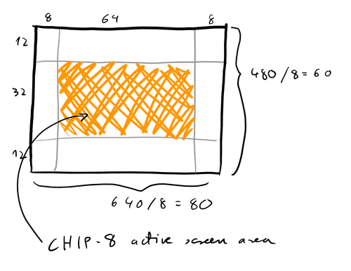
A low pixel clock frequency is useful for this project because I'm still learning the ropes with CλaSH, so getting just something to work is an achievement on its own; getting something to work efficiently, at a high clock rate, or using two separate clock domains for the video generator and the CPU would both be more advanced topics for a later version. So for this project, I'm going to go with 640⨯480: divided by 8, this gives us a screen layout that looks like this:
Signal generation from CλaSH
So out of all the 640⨯480 modes, we're going to use 640⨯480@60Hz for this, since the CHIP-8 also has a 60 Hz timer which we'll get for free this way. Let's write down the timing parameters; we'll need a 10-bit counter for both X and Y since the porches push the vertical size to 524.
data VGATiming n = VGATiming
    { visibleSize, pre, syncPulse, post :: Unsigned n
    }

data VGATimings w h = VGATimings
    { vgaHorizTiming :: VGATiming w
    , vgaVertTiming :: VGATiming h
    }

-- | VGA 640*480@60Hz, 25.175 MHz pixel clock
vga640x480at60 :: VGATimings 10 10
vga640x480at60 = VGATimings
    { vgaHorizTiming = VGATiming 640 16 96 48
    , vgaVertTiming  = VGATiming 480 11  2 31
    }
The output of the signal generator is the vertical and horizontal sync lines and the X/Y coordinates of the pixel being drawn; the idea being that there would be some other circuit that is responsible for ensuring the correct color data is put out for that coordinate. I've also bundled two extra lines to signal the start of a line/frame: the frame one will be used for the 60Hz timer, and the line one can be useful for implementing other machines later on: for example, on the Commodore 64, the video chip can be configured to interrupt the processor at some given raster line.
data VGADriver dom w h = VGADriver
    { vgaVSync :: Signal dom Bit
    , vgaHSync :: Signal dom Bit
    , vgaStartFrame :: Signal dom Bool
    , vgaStartLine :: Signal dom Bool
    , vgaX :: Signal dom (Maybe (Unsigned w))
    , vgaY :: Signal dom (Maybe (Unsigned h))
    }
For the actual driver, a horizontal counter simply counts up to the total horizontal size, and a vertical counter is incremented every time the horizontal one is reset. Everything else can be easily derived from these two counters with just pure functions:
vgaDriver
    :: (HiddenClockReset dom gated synchronous, KnownNat w, KnownNat h)
    => VGATimings w h
    -> VGADriver dom w h
vgaDriver VGATimings{..} = VGADriver{..}
  where
    vgaVSync = activeLow $ pure vSyncStart .<=. vCount .&&. vCount .<. pure vSyncEnd
    vgaHSync = activeLow $ pure hSyncStart .<=. hCount .&&. hCount .<. pure hSyncEnd
    vgaStartLine = hCount .==. pure hSyncStart
    vgaStartFrame = vgaStartLine .&&. vCount .==. pure vSyncStart
    vgaX = enable <$> (hCount .<. pure hSize) <*> hCount
    vgaY = enable <$> (vCount .<. pure vSize) <*> vCount

    endLine = hCount .==. pure hMax
    endFrame = vCount .==. pure vMax
    hCount = register 0 $ mux endLine 0 (hCount + 1)
    vCount = regEn 0 endLine $ mux endFrame 0 (vCount + 1)

    VGATiming hSize hPre hSync hPost = vgaHorizTiming
    hSyncStart = hSize + hPre
    hSyncEnd = hSyncStart + hSync
    hMax = sum [hSize, hPre, hSync, hPost] - 1

    VGATiming vSize vPre vSync vPost = vgaVertTiming
    vSyncStart = vSize + vPre
    vSyncEnd = vSyncStart + vSync
    vMax = sum [vSize, vPre, vSync, vPost] - 1
I hooked it up to a small test circuit, connected it to a small CCTV display I had lying around before I unpacked the bigger old VGA screen, and... nothing. This was frustrating because in the CλaSH simulator the sync timings looked right. Then Joe had this simple but brilliant idea to just blink an LED at 1 Hz using the pixel clock, and see if that is correct -- this immediately uncovered that I was using the wrong clock manager settings, and instead of a pixel clock of 25.125 MHz, it was running at 40 MHz. No wonder the signal made no sense to the poor screen... With that out of the way, I finally saw the test pattern:
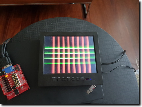
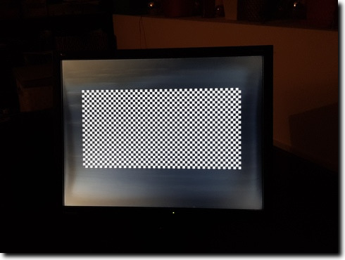
And so with a bit of bit truncation, I now have a checkers pattern displayed at the CHIP-8 resolution; and I've even ended up bringing out the larger screen:
The full code in progress is on GitHub; in particular, the version that generates the checkerboard pattern is in this code.